| CAD files | Sourcing | Component justification |
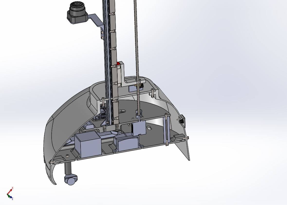
| Battery | Mockup created by me | · 12V 15000Ah Rechargeable Lithium-Ion Battery Pack . Battery must be sufficient for continuous usage. |
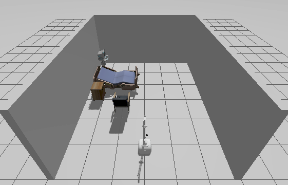
| pi | Obtained from GRABCAD | · Raspberry Pi 5 Single Board Computer (8GB) Quicker Deal As the robot will be simulated on ROs , a ROs compatible micro computer is necessary, thats why Rpi was selected. |
| Lidar sensor | Obtained from GRABCAD | Lidar for high resolution room mapping |
| Camera | Obtained from GRABCAD | 3D depth camera for high resolution object distance sensing. And accurate surface detection. |
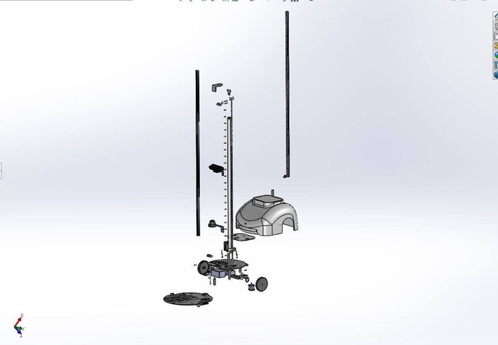
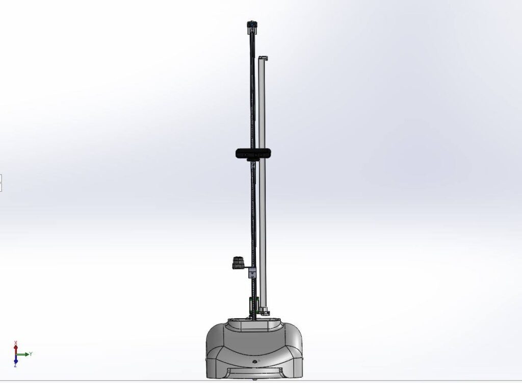
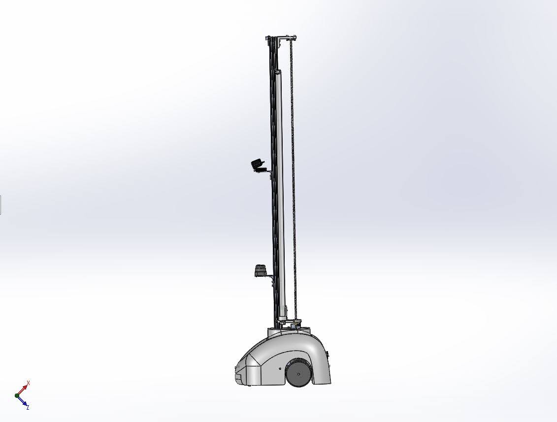
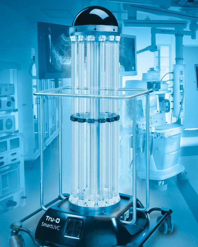
| UVC lamp | Mockup created by me | UVc lamp for disinfection. This is a vertical lamp . 75 Watts. If the lamp was too small, it would mean the robot would have to be too close to surfaces to sanitise, it would also take longer. However a lamp too large would mean larger power consumption and bigger battery requirement. However various lamps will be tested throughout the simulation |
| AC inveter 100 Watt | Mockup created by me | Inverter needed as UV-c lamps require Ac current |
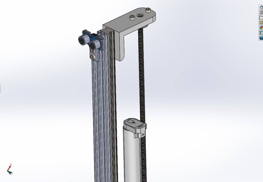
| Stepper motor 17 | Obtained from GRABCAD | Stepper motor needed to raise and lower the lamp. |
| linear guides | Mockup created by me | Linear guides to move the lamp along |
| T8 Lead Screw | Mockup created by me | To screw the t5 lamp in |
| Coupling | Created by me | Part of the lamp system |
| Bearing | Created by me | For the lamp system |
| Stepper driver | Obtained from GRABCAD | To power stepper motor and encoded motors. |
| Lamp ballast | Created by me | To modulate frequency supplied to the lamp |
| Lamp holders | Created by me | To house the uvc lamp |
| Wires | Created by me | Connection of componenets |
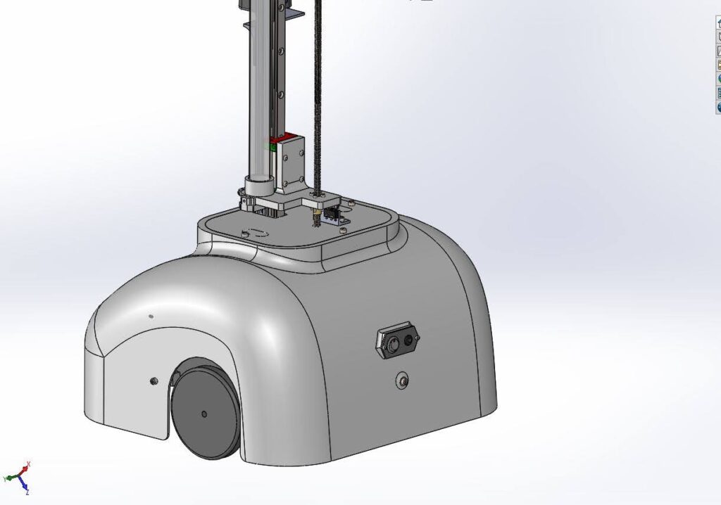
| Button | Obtained from GRABCAD | Activation of system |
| Power Jack | Obtained from GRABCAD | Power connection cable |
| Alumiun profile bracket | Created by me | Also part of lamp system |
| bearing | Created by me | Part of |
| limit switch | Obtained from GRABCAD | to act as a homing button for the light, to stop it crashing against base of bot. |
| SCREW | Solidworks Toolbox | To screw brackets together. |
| Motor bracket | Created by me | To hold motor in place |
| 2020 PROFILE | Created by me | The 2020 Profile Bracket provides essential structural support for the robot’s frame. It ensures secure attachment of various components, like motors, sensors, and the UVC lamp. Its modular design allows for easy customization and adjustments, making it an ideal choice for a strong, versatile robot structure. |
| Caster wheel | GrabCad | Castor wheel with a high load bearing offers balance without friction or slipping |
| Motor Encoders | Grab Cad | Motor encoders needed to calculate odometry and offer much higher positional accuracy. |
| Sonar sensor | Grab Cad | To protect the lamp |